INSTALLATION GUIDE
Locate mounting point
Find a desirable mounting point for the setup. For a setup containing gateway, battery and solar panel, the pole needs to be tall enough and strong enough to hold all three parts.
Mount gateway
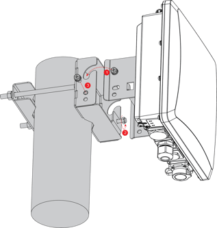
1. Fix the bracket included in the mounting kit on the bottom of the gateway with four M6*12 screws.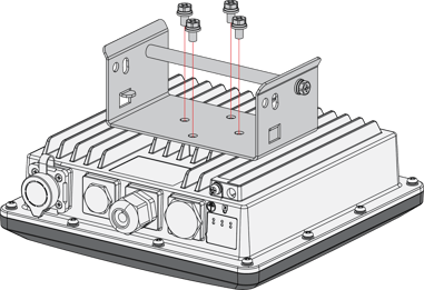
2. Install the Fiberglass antenna on the LORA1 port.
Remove the plastic protection from the antenna and from the gateway and screw on the antenna to the LoRa1 port.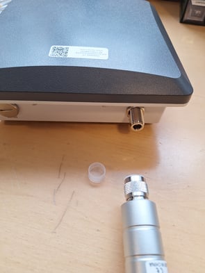
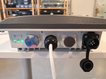
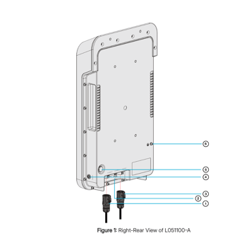
3. Install the power cable in the 4-point port on the right (The other end of the cable goes to the battery. This will be done later).
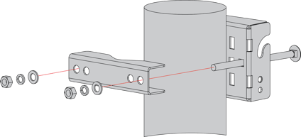
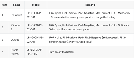
4. Position the pole clamps together around the pole, then tighten them with bolts, washers, and nuts.
5. Mount the enclosure and secure it to the bracket.
Mount Solar Panel
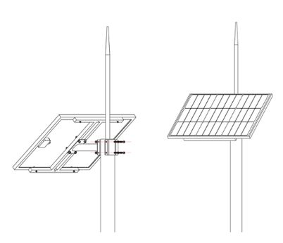
1. Use the kit provided to mount the solar panel. We have already fixed the big bracket on the solar panel, the only thing that needs to be attached is the mounting bracket onto the backside of the solar panel. 
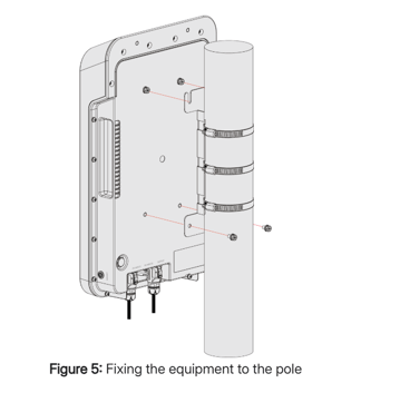
2. Then install the solar panel onto the pole as shown in the picture below.
The solar panel will harness most energy when the sun's rays strike its surface perpendicularly. Proper orientation and tilt of the panels help ensure that they generate maximum energy by exposing them to the highest intensity of sunlight for the longest possible period of time.
When it comes to positioning the solar modules, they must be oriented towards the solar or geographic south, which is the direction of the South Pole. If the solar module is located in the Southern Hemisphere, it should be oriented toward the true north.
Mount Battery Pack
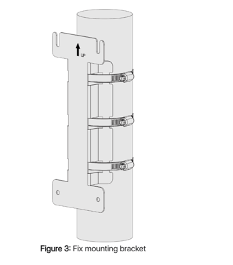
1. Fix the mounting bracket on the pole with three hose clamps.
2. Install two M6 screws on the back of the battery, leave a gap of about 3 mm.
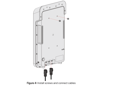
3. Connect the Cables to the circular connectors. The 4 pin cable connects to the Output port. The 2 pin cable connects to the PV Input 1 port. If a second Solar Panel needs to be connected, connect it to PV Input 2 port (not necessary in your case).
4. First, hang the equipment on the mounting bracket, then tighten the two screws that were left loose and screw the other two screws to secure the mount.
Power On
1. Power on the system by pushing the button on the battery.2. Ensure that the lights on the gateway are flashing:
- PWR, WLAN, LORA1 and LORA2 should be steady
- LTE should be flashing every few seconds
FINAL SETUP:
Weather protection
Rain Protection
To better protect the Ethernet cable gland and the antenna connector from the weather, you need to cover them with PVC tape.
- Clean the surface area of the connector that will be wrapped. Wrap a layer of PVC tape with a 50% overlap according to the rotation direction of the connector. Continue wrapping the PVC tape to about 10 mm below the end of the connector.
- Cut off about 50 cm waterproof tape. Stretch it to double the length. Wrap three layers around the connector with a 50% overlap. Hold the tape in place with your hand for a few seconds.
- Wrap three additional layers with PVC tape with natural uncoiling force and a 50% overlap. Make sure to cover the head and tail of the connector.
Lightning Protection
We also advise users to consider a lightning protection system to ensure a fully functional gateway without interruptions or damage.
- Antenna Grounding: It is recommended to install a lightning arrestor on all the antenna N-type terminals. The arrestors must be N-type Female to Male to fit the antenna and enclosure connectors. Ensure you use a 10 AWG or better wire to connect the screw terminals of the arrestors to the grounding rail mounted on the building wall (grounding bar in the case of field deployment).
- Gateway Grounding: Additionally, it is recommended to use another 10 AWG or better grounding wire to connect the screw terminal on the bottom-left side of the gateway casing to the grounding rail (bar).